

Accessing Aletyx Playground
Aletyx Playground is available both as a container that can easily be deployed into any container orchestration platform and as a local installation option.- Cloud
- Local container
The Aletyx Playground Interface
When you navigate to Aletyx Playground, you’ll see a welcome screen with several key areas: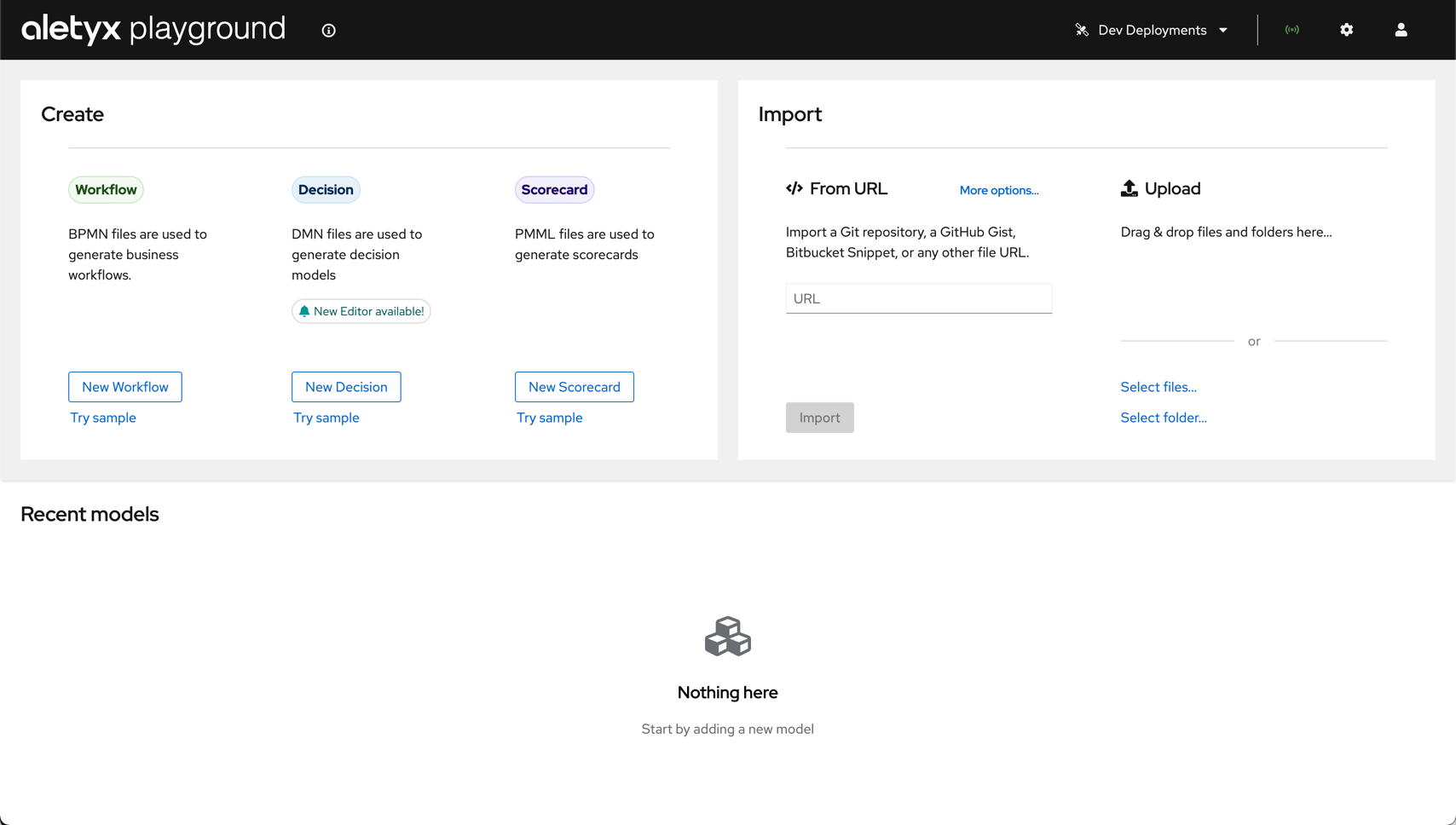
1. Creation Area
1. Creation Area
2. Import Area
2. Import Area
3. Projects Area
3. Projects Area
4. Toolbar
4. Toolbar
- Dev Deployments: Test deployments to connected Kubernetes or OpenShift clusters
- Extended Services: Connection to the DMN execution service for testing
- Settings (⚙️): Configure your Playground instance, including DMN version settings
- Profile (👤): Configure connections to Git providers and Kubernetes environments
Exploring Decisions with DMN
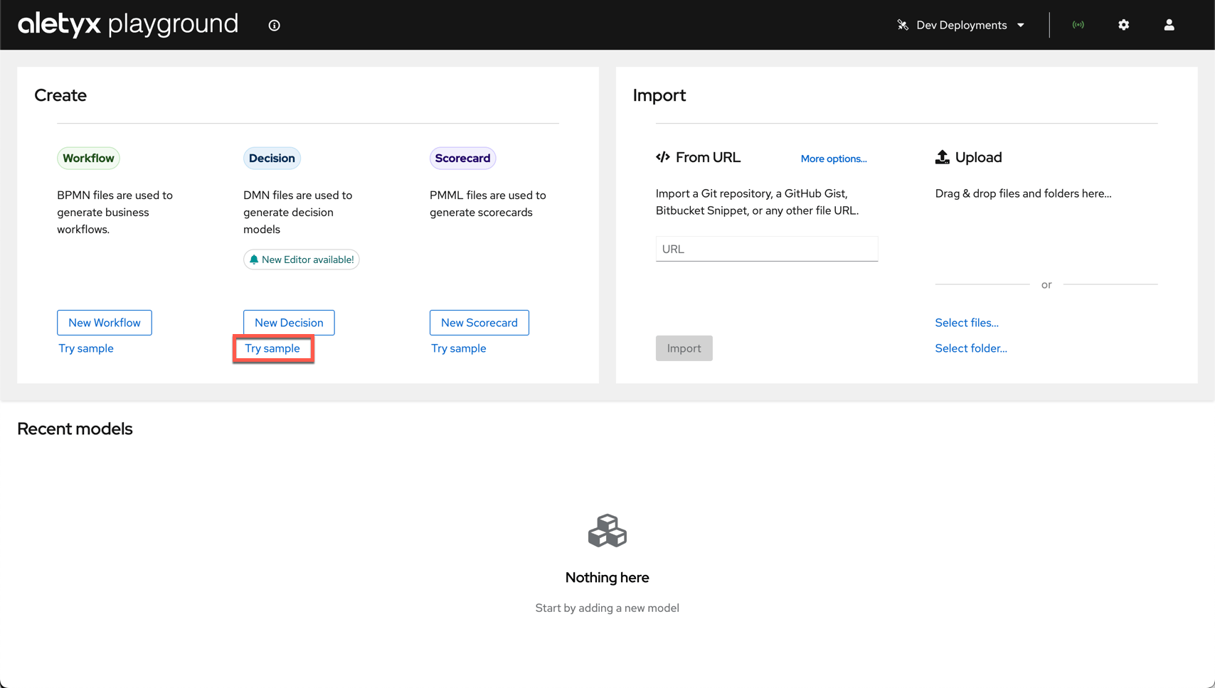
Let’s begin by exploring a sample Decision Model and Notation (DMN) model.Open the sample
Review the model
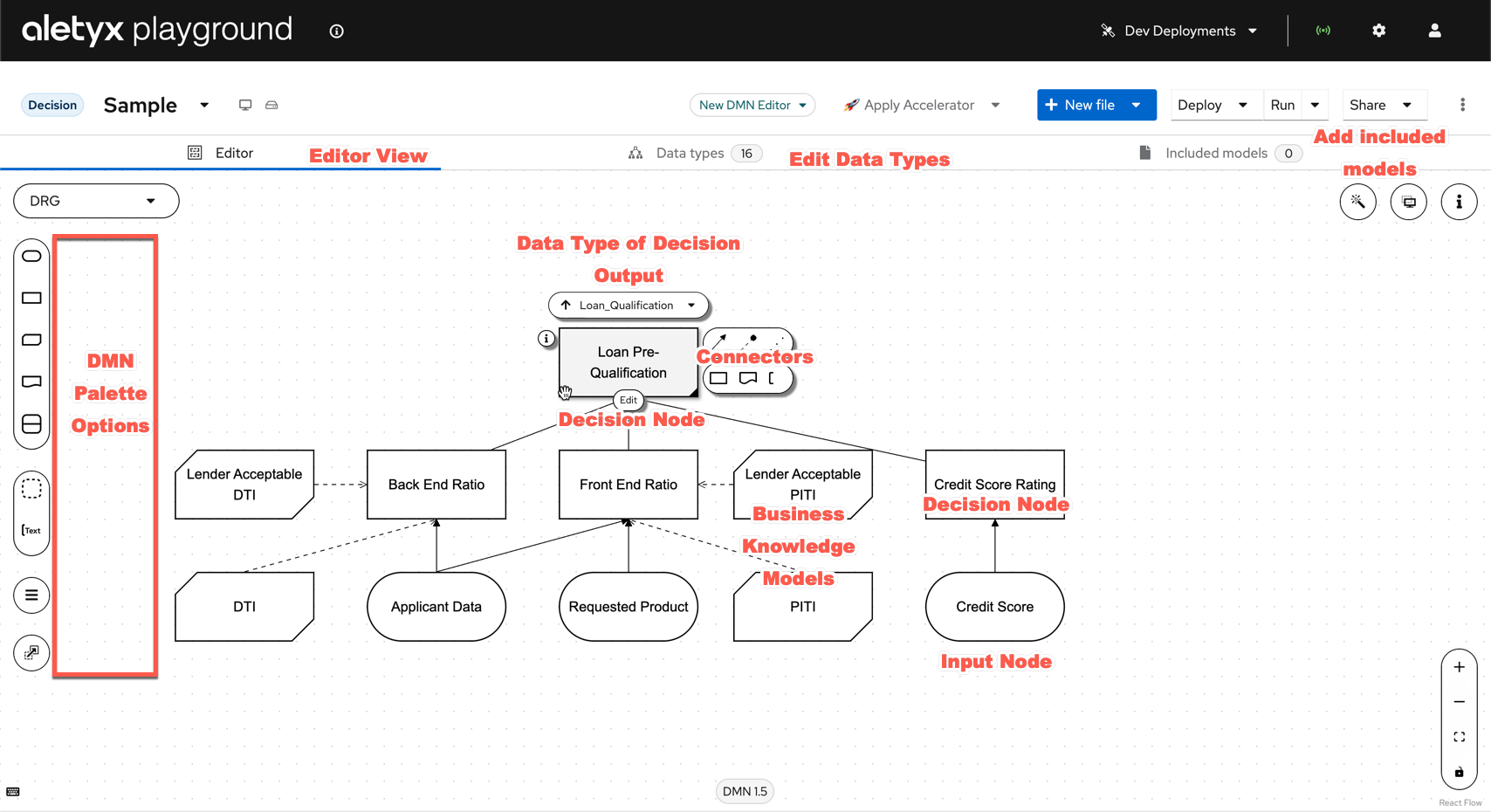
What each numbered part of the DMN editor does
What each numbered part of the DMN editor does
- Decision Editor — The currently active section of the editor, showing the DMN model or your current selection.
- Decision Connectors — From a decision, drag the connector lines to link it to the appropriate target — another decision or a knowledge source.
- Decision Output Type — The pulldown that maps the decision’s data type to a particular part of your model or structures.
- Data Types Editor — View, create, or edit the data types associated with the model.
- Included Models — Reference other models so decisions, data objects, and logic can be reused.
- Credit Score Rating decision node — The rectangle is a Decision Node; here it produces the Credit Score Rating from the Credit Score input.
- Credit Score input node — The oval is an Input Data Node — the applicant’s credit score — required to execute the decision.
- DRG node selector — Navigate between the nodes of the Decision Requirements Diagram.
- Annotations — Free-text annotations on the model; no executable impact, but great for explaining a model.
- Decision Input — In DMN an oval represents an input; these can be mapped to specific data structures or types.
- Decision Node — Places a decision on the diagram. A node with no inputs executes on invocation; if a requirement node (another decision or input) precedes it, that must complete first.
- Decision BKM (on the diagram) — A Business Knowledge Model lets FEEL, Java, or PMML supplement decision execution.
- Decision BKM (palette) — The palette shape for adding a Business Knowledge Model.
- Knowledge Source — Documents, committees, regulations, policies, or people that define how a decision should be made. Not executable.
- Decision Service — Captures decisions and exposes (or hides) them from execution.
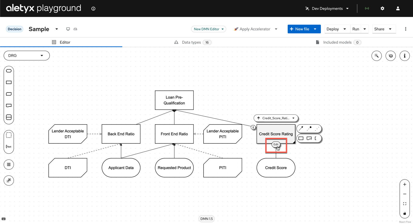
- Edit Decision — Click Edit below a node to edit that decision’s logic.
- Properties of selected item — Click the i icon (or press
i) to open the selected node’s properties.
View Sample DMN Model
View Sample DMN Model
Explore the model components
- Input Nodes: “Applicant Data” and “Credit Score”
- Decision Nodes: “Loan Pre-Qualification”
- Business Knowledge Models: Reusable decision logic
Open a decision
Inspect the decision table
What each numbered part of the decision table does
What each numbered part of the decision table does
- Input column / condition (e.g. “Credit Score.FICO (number)”) — Sets the condition on the FICO score. The dot notation takes the
FICOproperty from the input data. The rule rows below use the supplied score to determine the rating. - FEEL condition — Comparison expressions are common. Use brackets
[](inclusive) or parentheses()(exclusive) with..to write ranges. Note the Unique (U) hit policy requires that only a single rule can fire across the table. - Output column (e.g. “Credit Score Rating (Credit_Score_Rating)”) — Sets the decision’s output value when a row’s conditions match. Here it maps to the
Credit_Score_Ratingdata type. - FEEL output — The value set when the rule’s conditions are met. Strings use quotes (as shown), but this could just as easily be a number or a FEEL expression.
- Annotations column (optional) — Notes about each rule; ignored by the engine during evaluation.
- Hit Policy (the letter in the top-left cell) — Determines how an outcome is reached when multiple rules match: Unique (U), Any (A), Priority (P), First (F), and Collect (C) variants — Collect/Sum (C+), Collect/Min (C<), Collect/Max (C>), Collect/Count (C#).
- Rule 1 — Credit Score ≥ 750 — When the FICO score is 750 or greater, the Credit Score Rating is set to Excellent.
- Rule 2 — Credit Score 700 to < 750 — When the FICO score is inclusive of 700 to less than 750, the Credit Score Rating is set to Good.
- Rule 3 — Credit Score 650 to < 700 — When the FICO score is inclusive of 650 to less than 700, the Credit Score Rating is Fair.
- Rule 4 — Credit Score 600 to < 650 — When the FICO score is inclusive of 600 to less than 650, the Credit Score Rating is Poor.
- Rule 5 — Credit Score < 600 — When the FICO score is less than 600, the Credit Score Rating is set to “Bad”.
Interacting With Your Decision Model
When building DMN models within Aletyx Playground, you can take advantage of the fact that DMN includes an execution specification, making it super lightweight and portable. Aletyx Playground includes a built-in DMN runner that lets you see how the model would execute as it is written right now — no compilation. As you finish your change within a given cell or decision, you can see how your decision reacts in real time, all in the comfort of your browser!Run the model
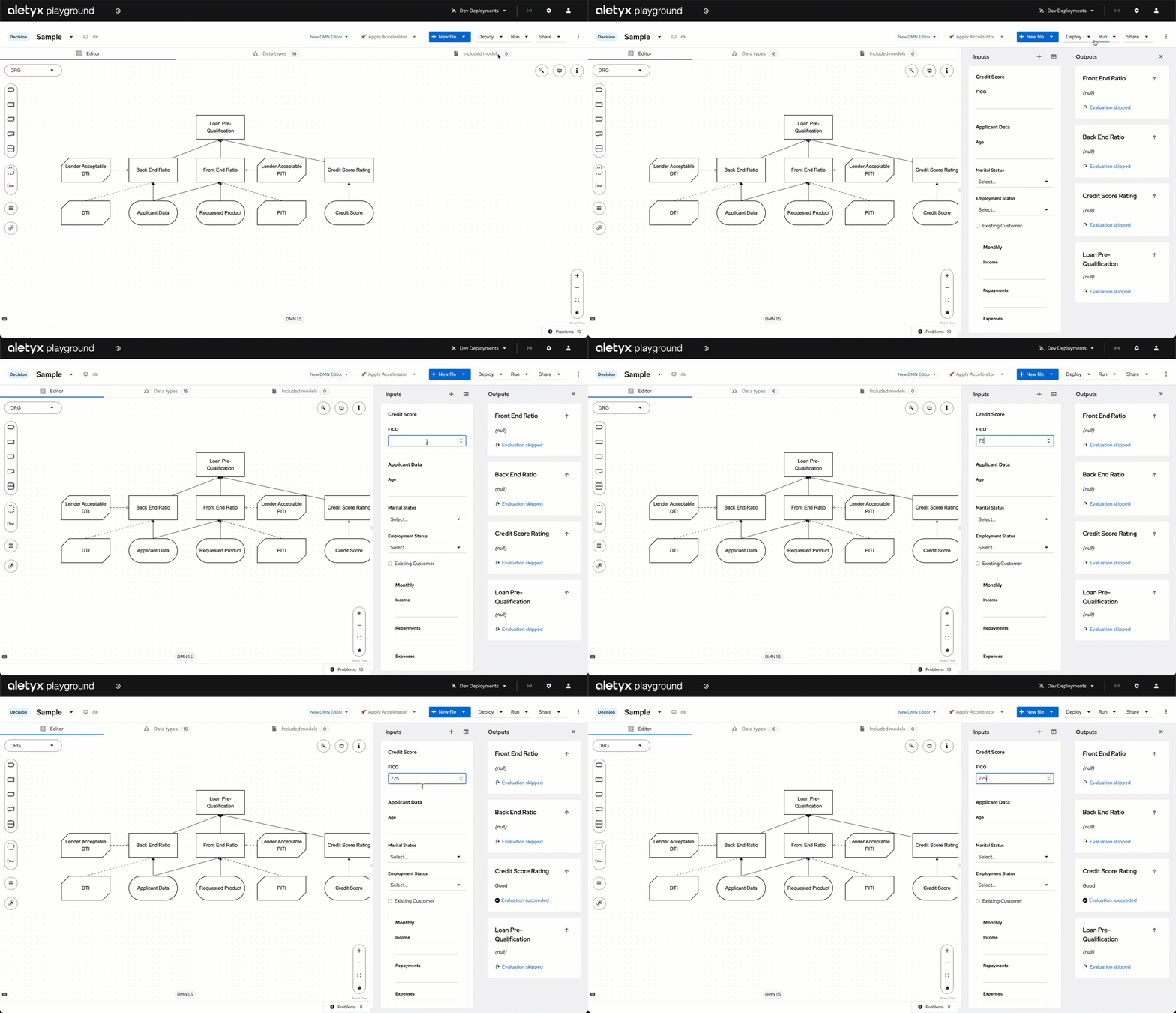
Test an input
Observe real-time output
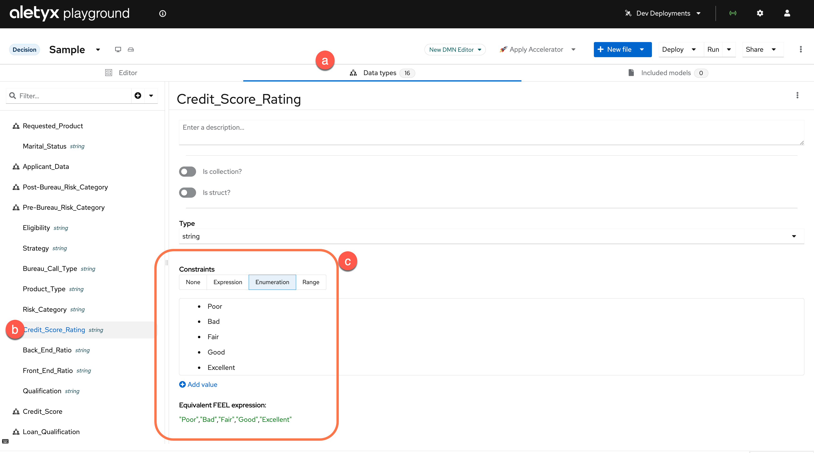
- Clicking Data Types at the top of the DMN model (2)
- Selecting the
Pre_Bureau_Risk_Categoryand selectingCredit_Score_Rating - You can see the example’s prefilled values of Poor, Bad, Fair, Good, Excellent — you can either add a new value here or change to work with one of these constrained values.
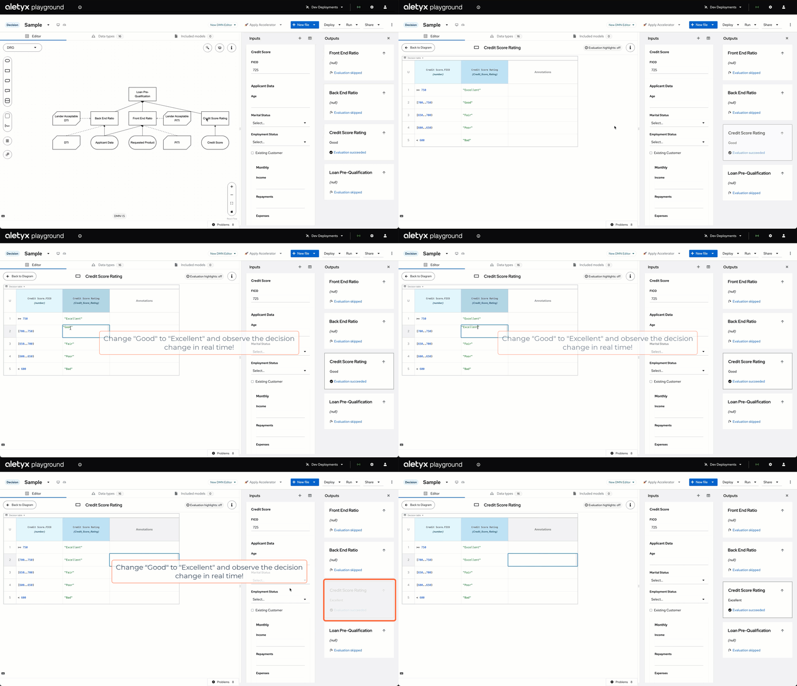
Modify the decision table
Creating Your First Project
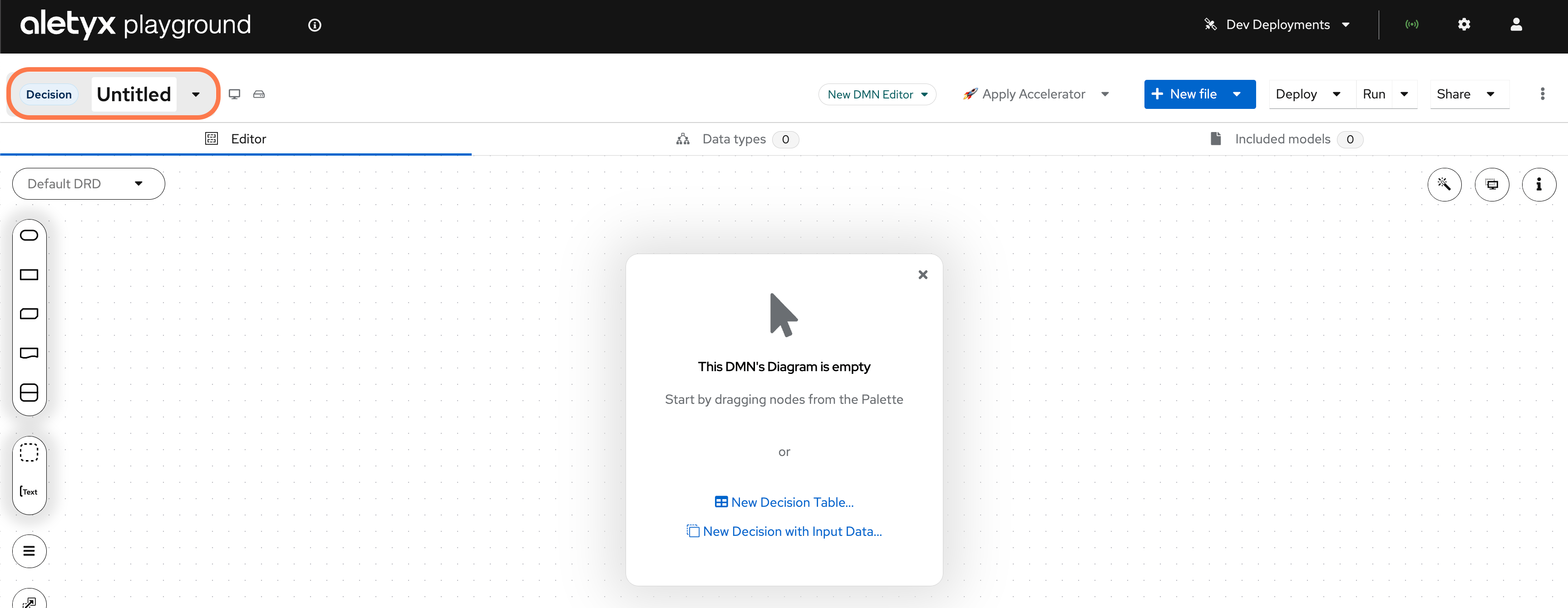
Now that you’ve explored the sample models, let’s create your own project.Create a new decision
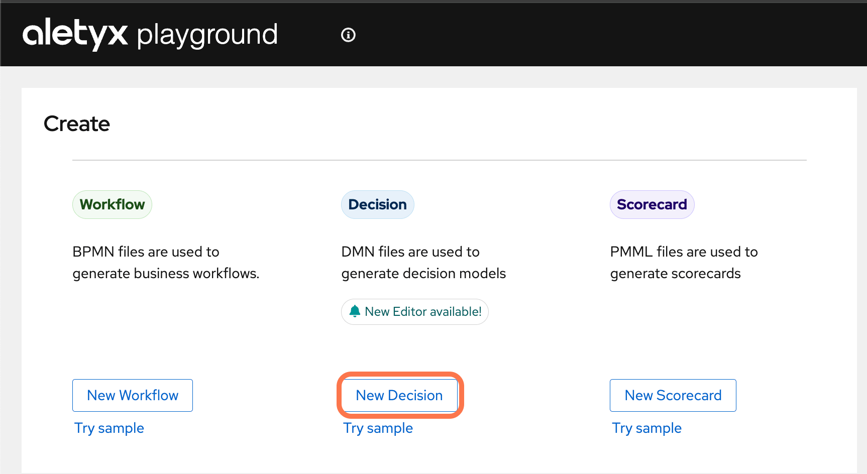
Name the model
Plan the project
- BPMN process models
- More DMN decision models
- Imported existing models
- A connection to a Git repository for version control
Basics of DMN modeling — A Top-Down or Bottom-Up Approach both work here!
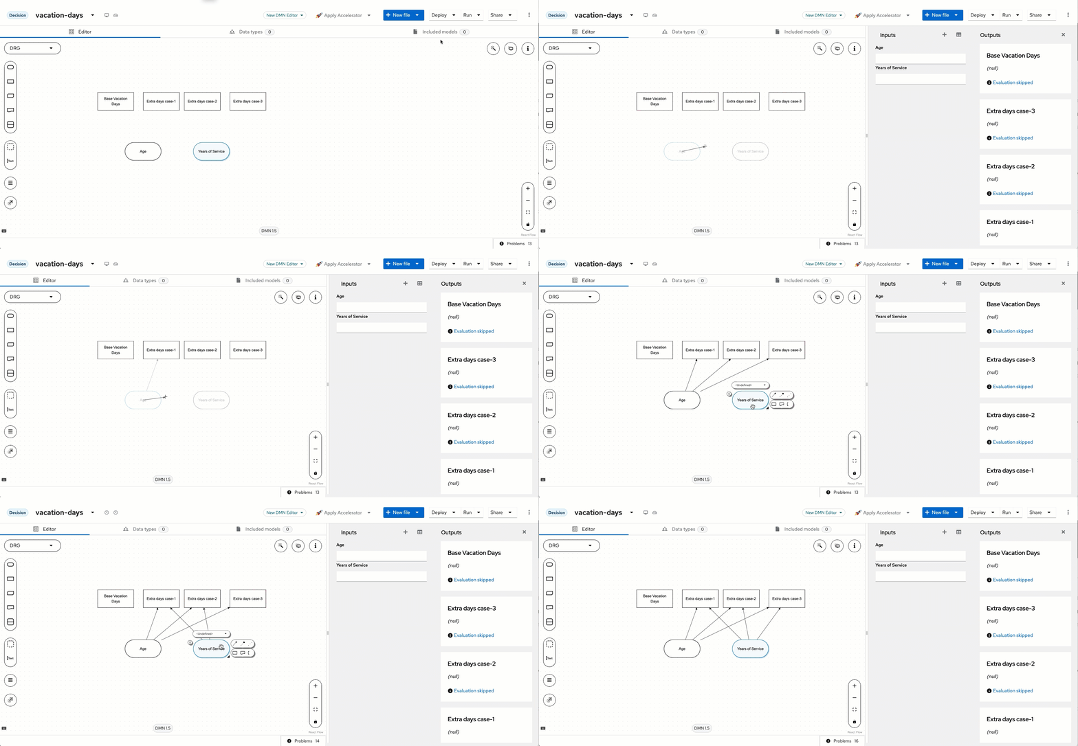
Now that the model is created, we need to create the base of the model. Our model can be designed from a top-down approach or bottom-up, given that we know most of the decision as it stands right now. There is a base level of days that will be used and three extra-days cases that can be created. We also know that there are two inputs for the decisions — Age and Years of Service. Since we know most of the decision design up front, let’s get started quickly! We can put 2 input nodes (the ovals) and four decision nodes (the rectangles) onto the DMN designer area. You can drag and drop these from the left-hand side and start changing the names.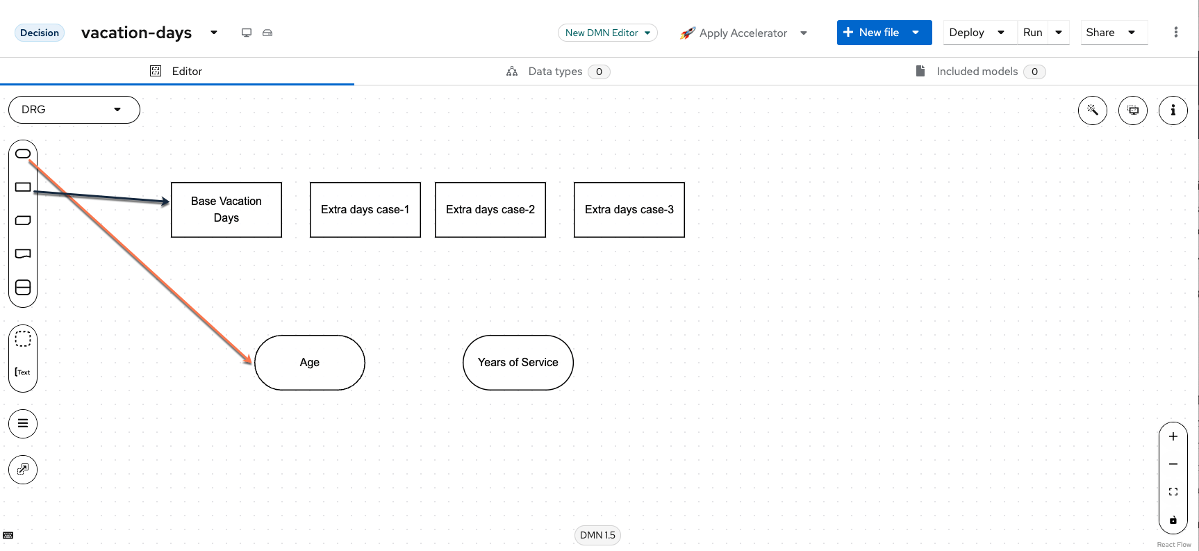
i key on your keyboard to instantly open it). This can also
be edited using the pulldown above the node for quicker change; the properties panel
can also provide extra context if needed.
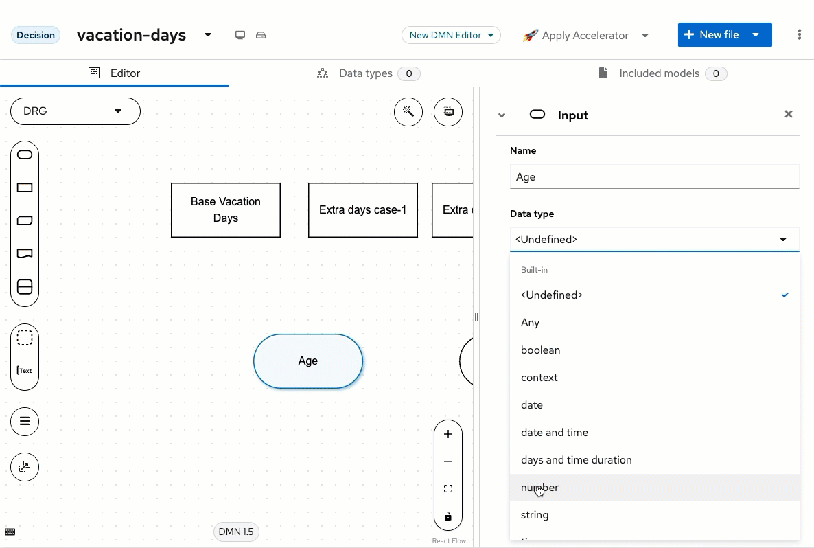
- Age — Data Type: number
- Years of Service — Data Type: number
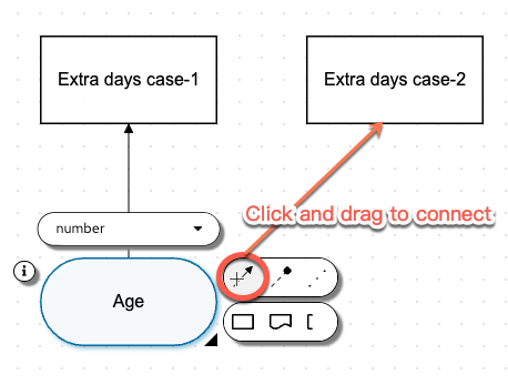
Click to see the process in action
Click to see the process in action
Building Extra Days Case-1
The first Extra days case is modeled by the scenario: “Employees younger than 18 or older than 60 will receive an extra 5 days; or greater than 30 years of service will receive 7 days.” To implement this we will build a decision table to model this logic. Note that our decision table is going to use the Age and Years of Service that we are taking from the input nodes.Click to see a preview of Extra Days Case-1
Click to see a preview of Extra Days Case-1
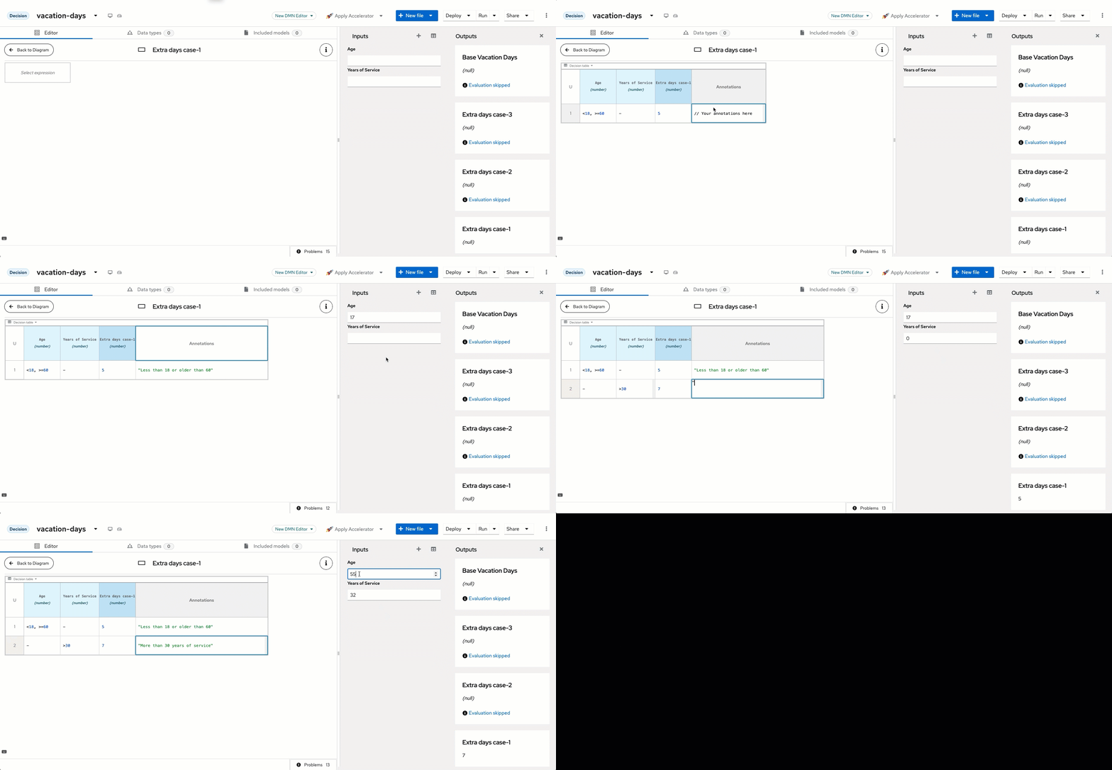
Open the decision editor
Set the expression type
Set the hit policy
Set a default output
null when
testing. To avoid issues with a null, set a default value on the output column for
the otherwise situations. Click the column header of Extra days case-1 and open the
property panel by clicking the i button on the decision header. Scroll down to
Default Output Entry. Since we’re just changing the default value of the column,
no expression language is needed — just set the value equal to 0. Once you leave
the Content box, the decision itself reacts.How to set default to 0
How to set default to 0
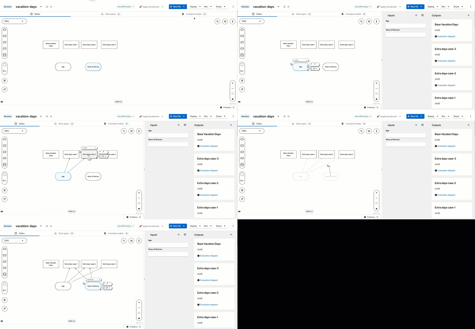
Return to the diagram
Building Extra Days Case-2
A lot of the same steps from before are going to be repeated for Extra Days Case-2, so let’s jump right in!Click to see a preview of Extra Days Case-2
Click to see a preview of Extra Days Case-2
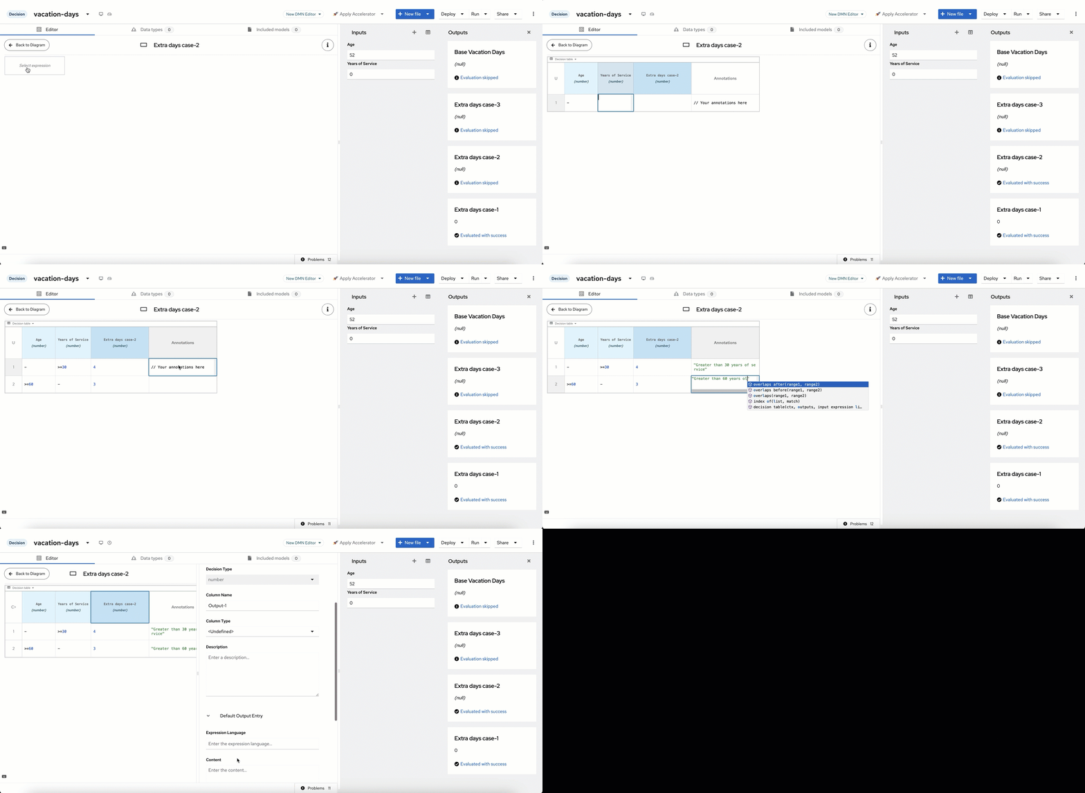
Open the decision editor
Select a decision table
Enter the rules
Return to the diagram
Building Extra Days Case-3
This will be done with the case that, based on years of service being between 15 and 30, you get 3 extra days of vacation; or if at least 45 (Age), you get 2 more days. Same as before, all default cases are set to 0.Click to see a preview of Extra Days Case-3
Click to see a preview of Extra Days Case-3
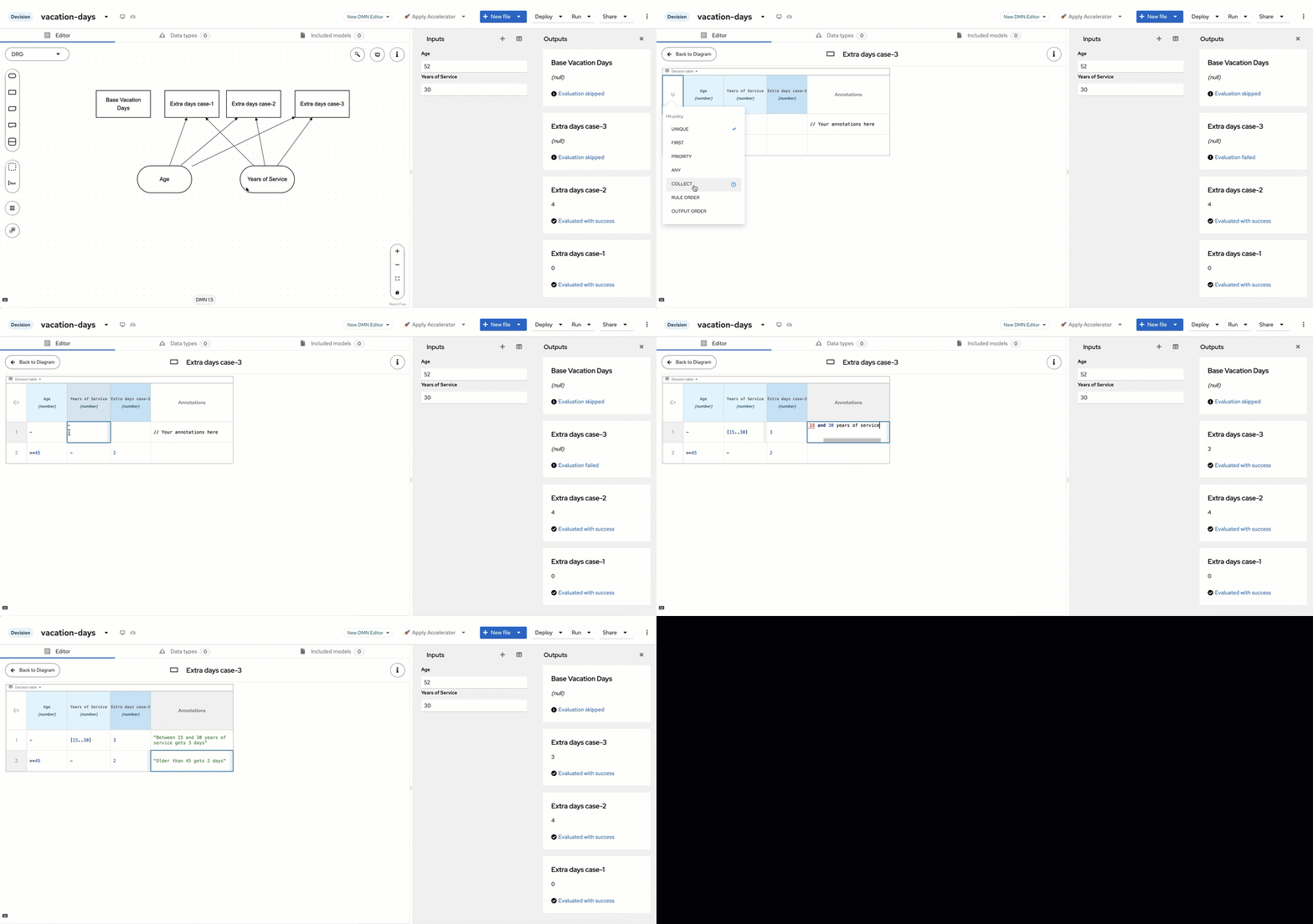
Summary of the Extra Days Cases
There’s an important component about the three extra cases worth visiting before moving on. You will notice that all three had both input nodes connected to them, and from that connection the DMN editor built the columns used as condition columns, with the decision node itself used as the output column. This greatly helps with building your decisions. As a Decision Requirements Diagram, the decision node uses the inputs to drive the decision based on the information requirements you give it. As we added more components to the diagram, it continued to execute them once the requirements were met. This is an essential part of DMN. Now that the extra days cases are each completed, we can revisit Base Vacation Days.Creating Base Vacation Days
The last base decision we need to create is the Base Vacation Days decision. On the base Decision Requirement Diagram, click on Base Vacation Days and click Edit. On the node’s “Select expression”, select Literal and input22, as the base number of
vacation days is 22.
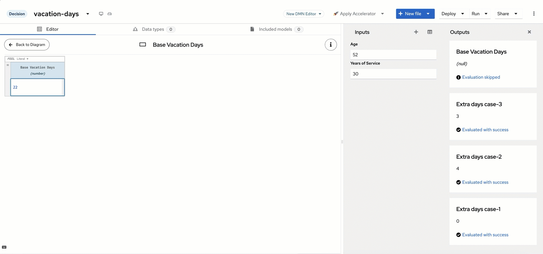
Click to see a preview of Base Vacation Days
Click to see a preview of Base Vacation Days
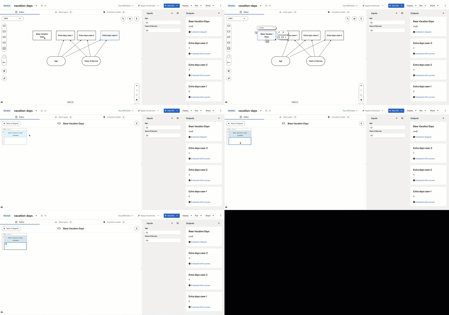
22 is entered, the Base Vacation Day
decision executes as soon as it is completed. This is because this decision has no
requirements on the age or years of service. If you were to delete the data from Age
and Years of Service, Base Vacation Days would remain at 22 and the others would return
null, as the data is assumed to be null/empty. This is the power of DMN: the decisions
that can be made at the time of execution will be made based on the requirements met.
As more data is obtained (Age/Years of Service), the nodes attached to it execute once
their requirements are met. Now that we have these nodes executing, we want to reach a
final decision made when all 4 components are executed.Building Total Vacation Days
Add the decision node
Click to see a preview of Drawing Total Vacation Days
Click to see a preview of Drawing Total Vacation Days
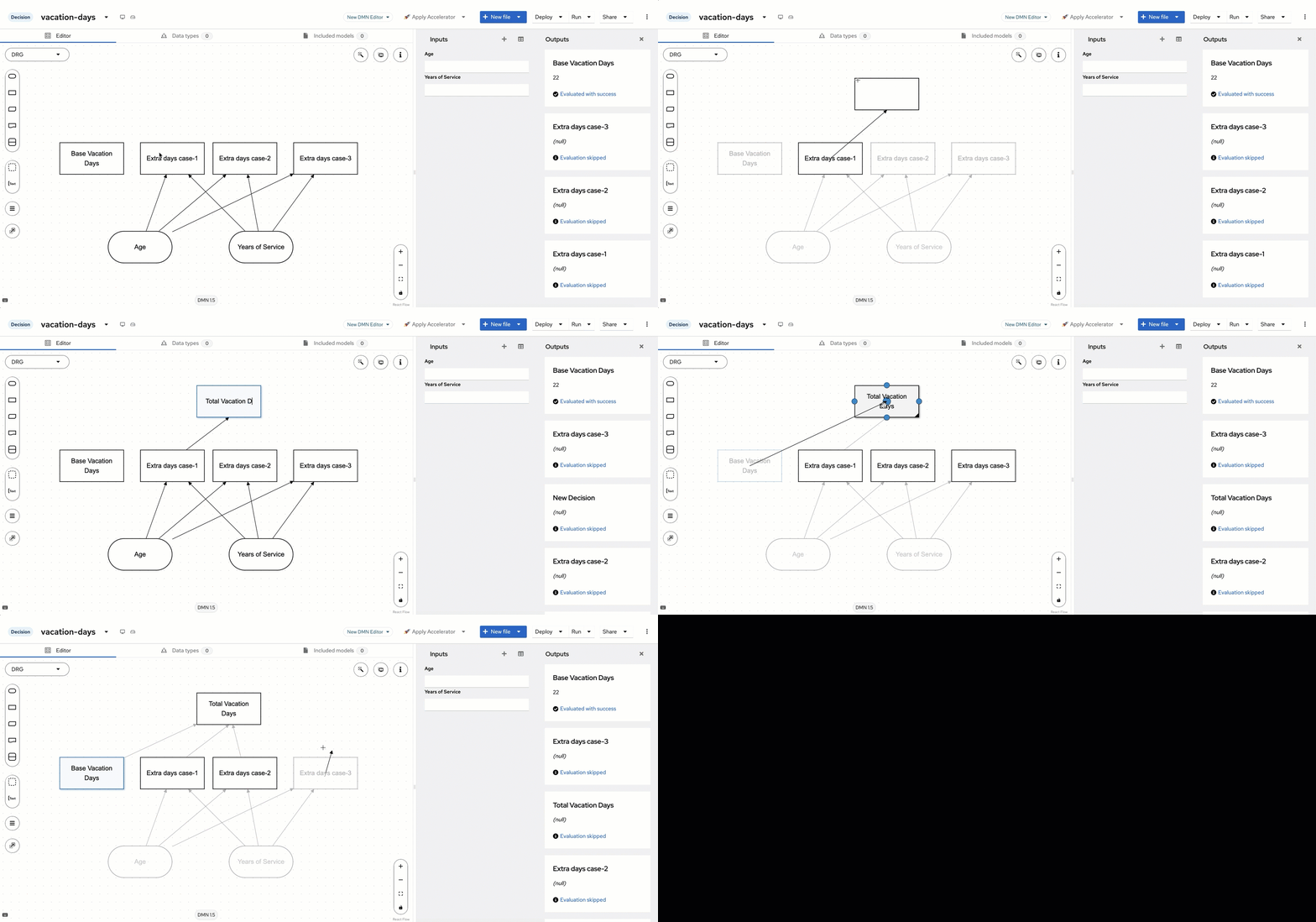
Connect the remaining nodes
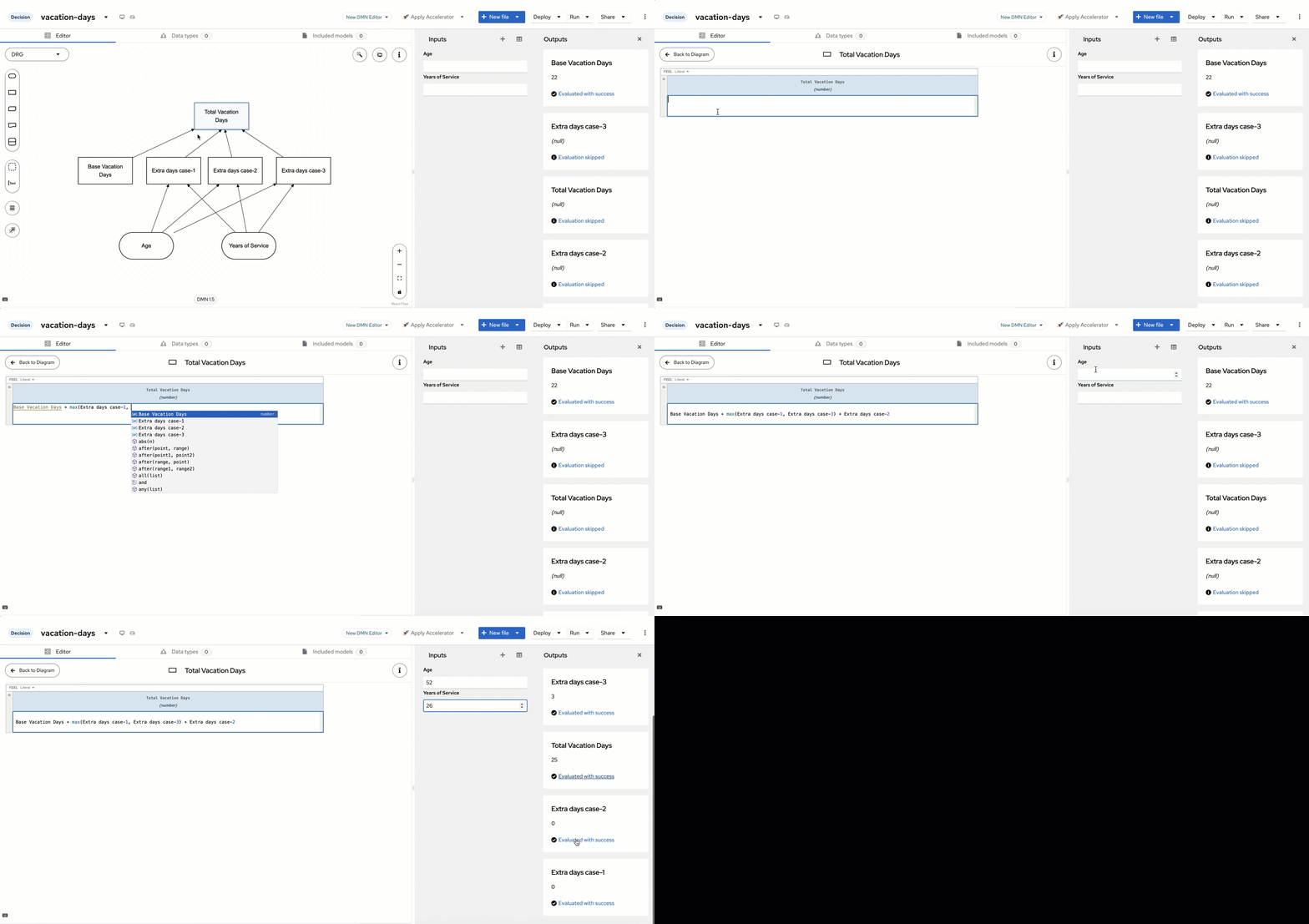
Enter the FEEL expression
Click to see a preview of Total Vacation Days
Click to see a preview of Total Vacation Days
Connecting to Git
To ensure your work is saved and versioned properly:Open Profile
Add a Git provider
Configure credentials
Connect your project
Select repository and branch
Next Steps
Now that you’re familiar with Aletyx Playground, here are some next steps to continue your journey:- Design a Complete Decision Model: Create a more complex decision model for a real-world scenario.
- Build an End-to-End Process: Design a complete business process with multiple tasks and decisions.
- Deploy to Kubernetes: Learn how to deploy your models to a Kubernetes environment.
- Integrate with Java Applications: Explore how to use your models in Java applications.
Decisions guide
Processes guide
Decision Analyst quickstart
What is DMN?
Additional Resources
- DMN Modeling Guide: Comprehensive guide to decision modeling.
- BPMN Modeling Guide: Detailed information on process modeling.
- Aletyx Playground API: Learn about the API for automation and integration.